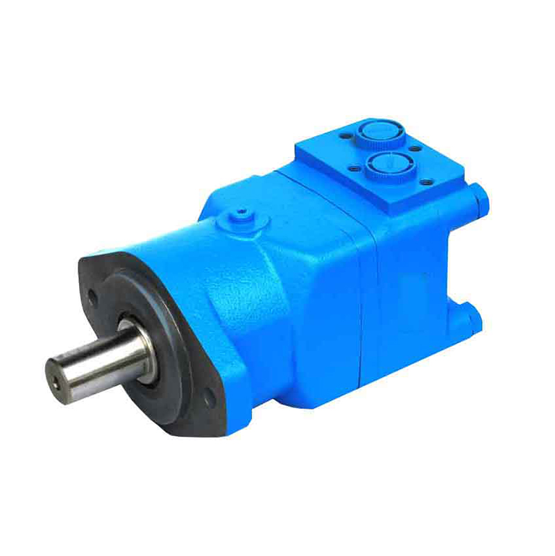
The BM hydraulic motor is an axial porting hydraulic motor. Its housing is cast from ductile iron with sufficient strength, making it suitable for applications with low loads and intermittent operation. The main features of the motor are as follows:
Adopts an axial oil distribution structure, featuring small size, high efficiency, and long service life.
The shaft seal can withstand high pressure and allows series or parallel connection for use.
Enables easy forward and reverse rotation with stable rotational speed.
Compared with other hydraulic motors, it offers high cost-effectiveness.
Type
Displacement (ml/rev)
Ratedpressure (Mpa)
Maxpressure (Mpa)
Speedrange (r/min)
Ratedoutputtorque (N.m)
Maxoutputtorque (N.m)
Maxpower (Kw)
BMR-50
51.7
14
20
10-775
93
135
7
BMR-80
80.5
14
20
10-750
152
216
10
BMR-100
100.5
14
20
10-600
194
270
10
BMR-125
126.3
14
20
10-475
237
338
10
BMR-160
160.8
14
10-375
310
433
10
BMR-200
200.9
14
20
10-300
369
509
8
BMR-250
252.6
11
16
10-240
380
540
6
BMR-315
321.5
9
13
10-190
380
540
5
BMR-400
401.9
7
11
10-160
380
540
4
BM3-80
80.5
17.5
22.5
10-810
194
271
14
BM3-100
100.5
17.5
22.5
10-750
242
318
16
BM3-125
126.3
17.5
22.5
9-600
303
373
16
BM3-160
160.8
16
22.5
7-470
358
459
14
BM3-200
200.9
16
22.5
6-375
438
576
14
BM3-250
252.6
12.5
20
6-300
440
700
11
BM3-315
321.5
12.5
20
5-240
551
831
10
BM3-400
401.9
10
17.5
5-180
560
865
8
BM3-500
471.1
10
17.5
5-155
636
1113
8
BM4-160
158.8
20
28
10-625
450
663
20.1
BM4-200
200.8
20
28
9-500
561
818
25.2
BM4-250
252.2
20
28
8-400
710
1021
25.2
BM4-320
317.5
20
28
7-312
902
1322
25.2
BM4-400
401.6
18
24
6-250
1008
1431
22
BM4-500
535.3
16
21
5-175
1121
1598
21
BM5-315
314.9
20
28
10-475
873
1293
32
BM5-400
399.7
20
28
9-375
1108
1650
32
BM5-500
496.6
20
28
8-300
1385
2060
32
BM5-630
617.8
18
24
6-238
1570
2249
32
BM5-800
787.4
16
21
5-187
1773
2481
32
BM5-985
969.1
14
18
5-154
1900
2399
24
BM6-800
759.6
16
21
5-200
1690
2220
35
BM6-1000
949.5
16
21
5-160
2160
2774
35
BM6-1250
1186.8
16
21
5-130
2650
3469
35
When the rotor rotates to form the minimum enclosed cavity, the oil discharge from this cavity is completed, and it waits for high-pressure oil to enter for work. As the rotor rotates further, the tooth cavity expands, and the oil distribution hole on the housing connected to this cavity should align with the oil inlet groove of the oil distribution sleeve. However, due to the excessive clearance of the spline shaft in the crawler hydraulic motor, the oil distribution sleeve lags behind the rotor and the oil distribution hole on the housing by an angle. This keeps the minimum tooth cavity connected to the oil discharge groove on the oil distribution sleeve, rather than connecting it to the oil inlet groove.
According to the rotation direction of the rotor in the diagram, the left side of the housing oil distribution hole corresponding to the minimum enclosed cavity is the oil discharge groove of the oil distribution sleeve, and the right side is the oil inlet groove. The dotted line indicates the correct position, while the diagonal line indicates the actual position. Therefore, this cavity cannot do work before it is connected to high-pressure oil, which reduces its mechanical energy. Since the cavity of the wheel-axle hydraulic motor is connected to the oil discharge groove, the displacement decreases and the volumetric efficiency drops.