Home > Products > BM Series

MCR05A520

所属分类:BM Series

浏览次数:7

发布时间:2025-11-24 23:26

联系我们

Details

Dimensions

Information

Product Features

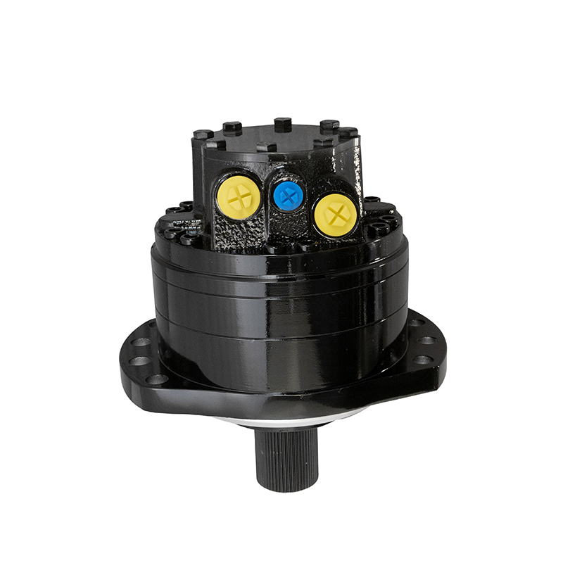
The YMS hydraulic motor is an internal-curve, multi-acting radial piston motor. Its main features are as follows:

Modular Design: The overall structure adopts a modular design with a plate-type stacking configuration. It is divided into four parts: the mechanical output module, hydraulic function module, oil distribution module, and mechanical braking module, facilitating compatibility with various mainstream optimized supporting systems.

High Efficiency: It adopts flat oil distribution technology, which has low sensitivity to pressure and temperature. This technology automatically compensates for wear between the oil distribution friction pairs, ensuring the motor maintains high volumetric efficiency for a long time. Meanwhile, the adoption of a roller-plunger structure simplifies the force transmission mechanism and improves mechanical efficiency.

High Operating Pressure and Excellent Low-Speed Performance: The stator curve design has been optimized to ensure output torque and stable rotational speed while reducing stator contact stress. Additionally, the stator is manufactured using new materials and processes, significantly increasing the operating pressure of the hydraulic motor, with a maximum pressure of up to 40 MPa. Due to the low inertia of the force transmission mechanism, the plunger pair is equipped with a sealed piston ring, and the roller stopper is made of friction-reducing material, the motor achieves high starting efficiency and excellent low-speed performance.

Ability to Withstand Radial and Axial Loads: With an independently arranged mechanical output module, as well as a large-diameter output shaft and bearings, the motor can withstand large axial and radial forces. It can be directly connected to a gear output or installed directly on the drive wheel of a vehicle.

Optional Mechanical Brake: It adopts a modular plate-type structure, which allows the integration of a mechanical braking device to achieve direct and safe service braking and parking braking of the output shaft.

Motor Displacement Control: Motors are categorized into single-displacement motors and dual-displacement motors. Single-displacement motors operate with full displacement output. Dual-displacement motors can realize both full-displacement and half-displacement output through control valve regulation, enabling speed control.

TypeDisplacement
(ml/rev)
Ratedpressure
(Mpa)
Maxpressure
(Mpa)
Theoreticaltorque
(10MpaN.m)
Speedrange
(r/min)
Maxpower
(Kw)
MCR03(A)16016025352255-32018
MCR03(A)22522525353585-32018
MCR03(A)25525525354055-28018
MCR03(A)28028025354455-26018
MCR03(A)32532525355175-24022
MCR03(A)36536525355805-24022
MCR03(A)40040025356365-24022
MCR05(A)38038025356045-22029
MCR05(A)47047025357485-22029
MCR05(A)52052025358275-22029
MCR05(A)56556525358995-22029
MCR05(A)680680253510825-22035
MCR05(A)750750253511945-17035
MCR05(A)820820253513055-15035
MCR10(A)780780253512405-17044
MCR10(A)940940253514945-15044
MCR10(A)11201120253517835-15050
MCR10(A)12501250253519905-14050
MCR10(A)13401340253521305-12050


Plunger assembly 3 is placed in the plunger hole of cylinder block 2 with a small clearance. The hydraulic pressure acting on the bottom of the plunger is transmitted to the cam surface of cam ring 1 through the roller.

When high-pressure oil enters the oil distribution shaft and flows into the plunger cylinder holes in the working section through the oil distribution window, the corresponding plunger assembly is pressed against the cam surface of cam ring 1 (housing). At the contact point, the cam surface of the cam ring exerts an eccentric force on the plunger. This eccentric force N acts on the common normal plane at the contact between the cam surface of the cam ring and the roller. This normal eccentric force N can be decomposed into an axial force Pₕ and a circumferential force T. Pₕ balances the hydraulic pressure at the bottom of the plunger, while the circumferential force T overcomes the load torque and drives cylinder block 2 to rotate. Under this working condition, the cam ring and the oil distribution shaft do not rotate. At this time, the plungers corresponding to the oil return section of the cam ring move in the reverse direction, and the hydraulic oil is discharged through the oil distribution shaft.

At the moment when plunger assembly 3 transitions from the working section of the cam ring’s cam surface to the oil return section, the oil supply and oil discharge channels are closed. To ensure the continuous rotation of the rotor, the internal curve hydraulic motor must ensure that there is always a plunger assembly in the oil inlet section for work at any moment. Therefore, there must be no structural situation where there is an odd common divisor between the number of acting times and the number of plungers z, or where x = z (Note: The variable "x" in the original text is not explicitly defined; it is retained here as in the original context).

For BM series hydraulic motors and Poclain motors, the above working principle and structural constraints apply consistently.
    MCR05A520


上一页:MCR3D400L40Z32A0M 下一页:MCR10A1340